


Views: 0 Author: Site Editor Publish Time: 2026-08-07 Origin: Site


Specifying the wrong pump guarantees chronic mechanical failures, excessive energy consumption, and catastrophic system downtime. Reliance on outdated specifications, arbitrary safety margins, or incomplete system data leads directly to cavitation, premature seal failure, and severe vibration. You cannot afford to guess when matching hydraulic output to piping network realities. Up to 85% of a pump’s lifecycle impact is tied to energy draw and maintenance intervals. Selecting the right equipment requires precise engineering and rigorous environmental assessment. Facility managers, mechanical engineers, and procurement teams need a reliable pump selection guide to evaluate technical requirements, mitigate implementation risks, and ensure long-term hydraulic stability. Understanding the most common engineering oversights prevents premature equipment degradation and maintains peak operational efficiency.
Match System Curves to Pump Curves: Operating outside a pump’s Best Efficiency Point (BEP) accelerates mechanical wear and exponentially increases energy costs.
Calculate NPSH Accurately: Failing to verify Net Positive Suction Head Available (NPSHa) against the manufacturer's required NPSHr guarantees cavitation and premature impeller destruction.
Account for Fluid Dynamics: Temperature, viscosity, and specific gravity drastically alter performance requirements, especially when specifying a hot water circulation pump or handling corrosive fluids.
The most common point of failure in fluid handling infrastructure is a direct mismatch between the physical realities of the piping network and the hydraulic output of the equipment. When engineers fail to accurately calculate system resistance, the resulting hydraulic instability destroys internal components. Proper circulating pump selection requires strict adherence to mathematical realities rather than estimated safety factors. You must map the exact friction losses through every valve, fitting, and straight pipe run.
Engineers frequently add compounded safety factors during the design phase. A mechanical engineer might add a 10% margin to the flow requirements, and the piping contractor might add another 10% to the head requirements to cover unknown field routing. This pushes the pump to operate at the far right of its performance curve, a condition known as run-out. Conversely, under-sizing leads to an inability to meet peak demand and continuous motor overload.
Oversizing causes excessive flow rates and high energy consumption. It creates severe internal turbulence within the volute. This turbulence leads to increased radial thrust, which bends the shaft during operation. Shaft deflection forces the mechanical seal faces to open slightly, allowing particulates to enter and destroy the seal. The deflected shaft also places massive uneven loads on the bearings, causing them to spall and fail prematurely. Under-sizing causes chronic system underperformance. The motor draws excessive current trying to meet the system demand, leading to premature insulation breakdown and frequent thermal trips.
You must mandate precise calculation of actual system resistance and flow requirements using established Hazen-Williams or Darcy-Weisbach equations. Utilize variable frequency drives (VFDs) rather than oversized impellers to handle anticipated future capacity. This allows the system to adapt to changing demands without compromising mechanical integrity.
Sizing Error | Hydraulic Impact | Mechanical Consequence | System Result |
|---|---|---|---|
Oversized Pump | Operation at run-out (far right of curve) | Shaft deflection, bearing spalling, seal leaks | Excessive energy draw, high vibration, frequent rebuilds |
Undersized Pump | Operation at dead-head (far left of curve) | Thermal buildup, radial thrust imbalance | Inadequate flow, continuous motor overload, tripped breakers |
Mismatched Impeller Trim | Incorrect head generation | Internal recirculation at the impeller eye | Erosion of impeller vanes, unstable discharge pressure |
The Best Efficiency Point (BEP) is the specific point on the pump curve where radial forces on the impeller are perfectly balanced. At this point, energy transfer from the motor to the fluid is optimal, and the fluid moves through the volute with minimal turbulence. Operating at the BEP ensures the longest possible lifespan for bearings and seals because internal mechanical stresses are minimized.
A flawed practice involves selecting a pump based on absolute maximum theoretical flow. This peak flow rarely occurs in actual operation. Sizing for an extreme edge case forces the pump to run inefficiently for 99% of its operational life. When a pump operates far to the left of its BEP (reduced flow), fluid recirculates violently at the impeller eye and discharge tips. This recirculation causes low-frequency vibration and rapid erosion of the impeller material.
Request and carefully review performance curves from manufacturers. Ensure the continuous duty point aligns closely with the BEP. Reject selections that push the operating point to the extreme left or right edges of the curve, regardless of theoretical peak demands.
Identify the normal, continuous operating flow rate of your system.
Plot this flow rate on the manufacturer's published performance curve.
Verify that the operating point falls strictly between 80% and 110% of the BEP.
If the point falls outside this range, select a different pump size or adjust the impeller trim.
Confirm that the selected operating point does not intersect with the manufacturer's minimum continuous stable flow (MCSF) line.
Cavitation remains the leading cause of premature circulating pump degradation. Cavitation occurs when the pressure at the pump suction drops below the vapor pressure of the fluid. The fluid boils, creating vapor bubbles. As these bubbles pass into the higher-pressure zones of the impeller, they collapse violently. This collapse blasts microscopic pieces of metal off the impeller, sounding like gravel passing through the casing.
You must differentiate between NPSH Available (NPSHa) and NPSH Required (NPSHr). NPSHa is a function of your system design. You calculate it using absolute atmospheric pressure, static suction head, friction losses in the suction piping, and the vapor pressure of the fluid. NPSHr is a function of the specific pump design and is determined by the manufacturer through physical testing. If NPSHr exceeds NPSHa, cavitation is mathematically guaranteed.
Establish a strict engineering rule. NPSHa must exceed NPSHr by a minimum safety margin of 3 to 5 feet across all operating conditions. Calculate this margin at the maximum expected fluid temperature and the highest expected flow rate, as these conditions represent the worst-case scenario for suction pressure. Never assume standard atmospheric pressure if your facility is located at a high elevation, as altitude significantly reduces NPSHa.
Variable | Definition | Impact on Cavitation Risk |
|---|---|---|
Atmospheric Pressure | Absolute pressure pushing down on the fluid source | Higher elevation lowers atmospheric pressure, reducing NPSHa and increasing risk. |
Static Suction Head | Vertical distance from fluid level to pump centerline | Suction lift (fluid below pump) drastically reduces NPSHa. |
Friction Loss | Resistance from suction piping, valves, and strainers | Dirty strainers or undersized pipes increase friction, lowering NPSHa. |
Vapor Pressure | Pressure at which the fluid boils at a given temperature | Higher fluid temperatures increase vapor pressure, severely reducing NPSHa. |
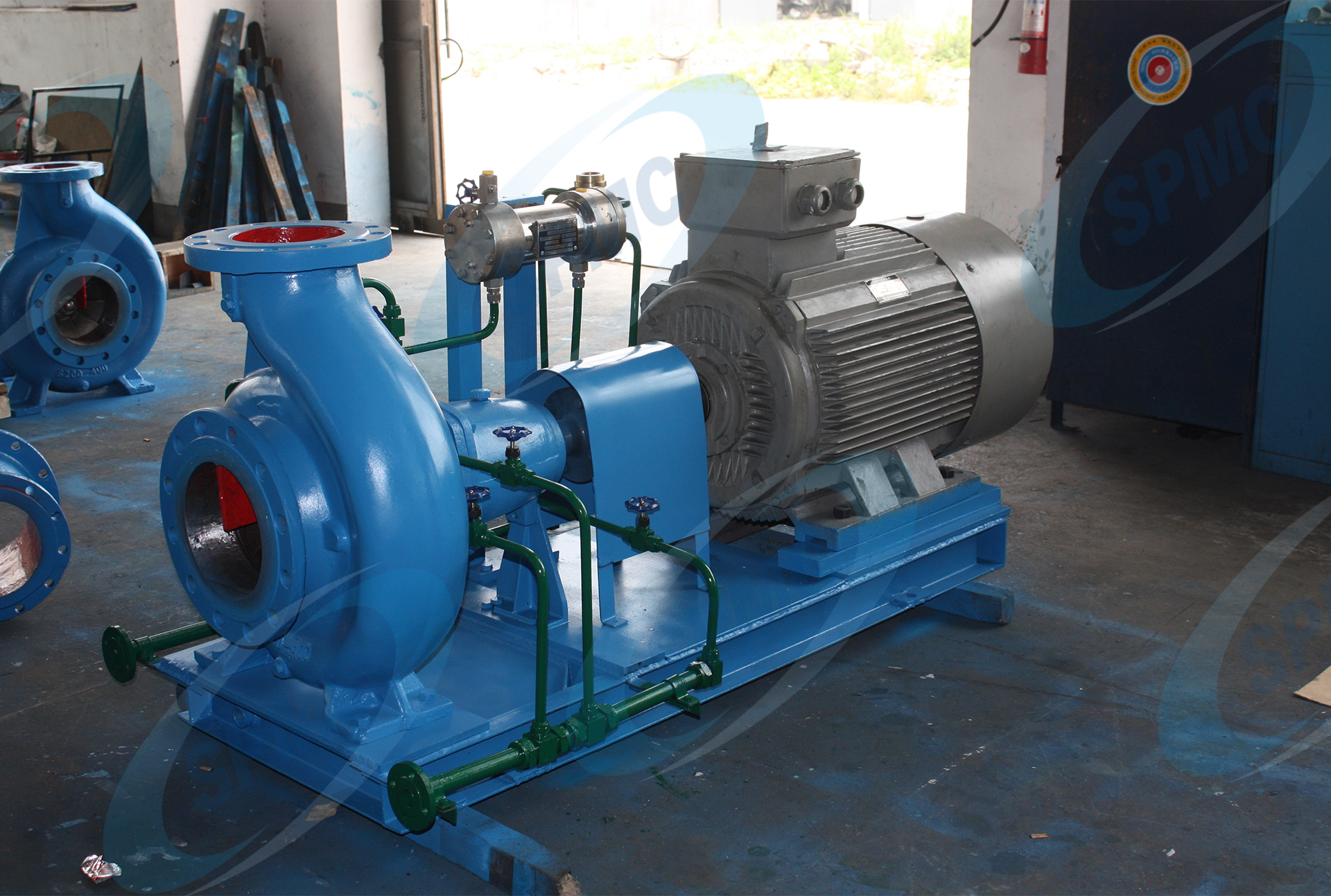
A unit that performs perfectly on paper will fail rapidly if specific environmental, physical, and fluid conditions are ignored. The wet-end materials, seal configurations, and motor enclosures must match the harsh realities of the installation site. Ignoring thermodynamics, fluid properties, and piping geometry leads to rapid material degradation and unstable hydraulics.
Fluid characteristics dictate pump materials and seal types. Pumping clean water at room temperature requires entirely different specifications than pumping aggressive chemicals, glycol mixtures, or high-temperature fluids. You must account for specific gravity, viscosity, and vapor pressure during the specification phase.
When selecting a hot water circulation pump, you face critical thermodynamic challenges. As water temperature rises, its vapor pressure increases significantly. This drastically reduces your NPSHa. You must account for these vapor pressure changes to prevent flashing and cavitation inside the volute. High temperatures also require specialized mechanical seals and elastomers like EPDM or Viton to prevent leaks. Standard Buna-N seals will harden, crack, and fail rapidly when exposed to temperatures above their rated limits.
Heavier or more viscous fluids require motor derating. Viscous fluids create more internal friction, requiring more brake horsepower to move the same volume. The formula for brake horsepower includes specific gravity as a direct multiplier. If you pump a fluid with a specific gravity of 1.2, the pump requires 20% more horsepower than it would for water. You need specific impeller designs, such as open or semi-open impellers, to prevent motor overload and clogging when handling fluids with higher specific gravity or suspended solids.
Friction loss through pipes, valves, fittings, and heat exchangers determines the total dynamic head the pump must overcome. Miscalculating this resistance leads directly to sizing errors. Furthermore, the physical compatibility of the suction piping layout is critical. You must maintain straight pipe runs before the suction flange—typically 5 to 10 pipe diameters—to prevent turbulent flow from entering the impeller eye. Installing an elbow directly on the suction flange causes uneven fluid loading, which pushes the impeller off-center and destroys the radial bearings.
For an HVAC circulating pump, dynamic head changes constantly. As control valves open and close in response to building loads, the system curve alters in real-time. The pump must be able to ride its performance curve without entering dead-head or run-out conditions as these valves modulate. You must also ensure eccentric reducers on the suction side are installed flat-side up to prevent air pockets from forming and passing into the casing.
Maintain 5 to 10 diameters of straight, unobstructed pipe immediately upstream of the suction flange.
Install eccentric reducers with the flat side facing up to eliminate trapped air pockets.
Never install a valve directly on the suction flange; move it upstream of the straight pipe run.
Support all piping independently to ensure pipe strain is not transferred to the pump casing.
Use long-radius elbows instead of short-radius elbows to minimize friction loss and turbulence.
The pump wet-end represents only half the system. Incorrect motor sizing and inadequate control specifications drive up electrical consumption and reduce operational flexibility. Failing to integrate modern control strategies leaves systems vulnerable to inefficiencies and mechanical stress. You must specify the driver and the controls with the same rigor as the hydraulics.
Fixed-speed operation relies on throttling valves to control flow. This is mechanically equivalent to driving a car with the accelerator pressed to the floor while using the brakes to control your speed. It wastes massive amounts of energy and puts unnecessary stress on the piping network. Variable speed operation uses VFDs to slow the motor, matching output exactly to system demand.
The Affinity Laws govern this relationship. Flow is directly proportional to shaft speed. Head is proportional to the square of the shaft speed. Power is proportional to the cube of the shaft speed. A 20% reduction in pump speed yields nearly a 50% reduction in energy consumption. Specifying VFD compatibility is non-negotiable for modern fluid handling systems with variable demands. You must specify motors with inverter-duty insulation (Class F or H) to withstand the voltage spikes generated by VFDs.
However, you must manage the implementation risks. Operating VFDs at speeds too low to maintain minimum flow requirements causes thermal buildup inside the casing. The fluid absorbs the motor's heat, eventually boiling and destroying the mechanical seals. Always program a minimum speed setpoint into the VFD to ensure sufficient cooling flow, or install a minimum flow bypass line back to the source tank.
Environmental risks dictate motor enclosure standards. Installing an Open Drip Proof (ODP) motor in a washdown environment or a dusty industrial plant guarantees a short lifespan. You must map environmental hazards—such as moisture, chemical exposure, and airborne particulates—to the correct enclosure, such as Totally Enclosed Fan Cooled (TEFC) or Explosion-Proof standards. Washdown environments require severe-duty epoxy coatings and sealed conduit boxes.
Underestimating motor power is a frequent error. You must specify a non-overloading motor for the end of the curve. If the system resistance drops unexpectedly, the pump will run out on its curve, drawing maximum horsepower. If the motor is only sized for the BEP, it will trip breakers or burn out during these high-flow events. Always check the brake horsepower curve and ensure the selected motor nameplate rating exceeds the maximum possible power draw at any point on the performance curve.
Motor Enclosure Type | Protection Level | Ideal Application Environment |
|---|---|---|
Open Drip Proof (ODP) | Vents allow ambient air to cool windings. Protects against falling water drops up to 15 degrees from vertical. | Clean, dry, indoor mechanical rooms with controlled climates. |
Totally Enclosed Fan Cooled (TEFC) | No outside air enters the motor. An external fan blows air over the ribbed frame. | Dusty, dirty, or damp industrial environments. Outdoor installations. |
Explosion Proof (XP) | Contains internal explosions without igniting external hazardous atmospheres. | Chemical plants, refineries, or areas with combustible dust/gases. |
Washdown Duty | Sealed bearings, epoxy paint, and moisture-resistant windings. | Food processing, breweries, or areas subject to high-pressure hose cleaning. |
Treating heavy rotating equipment as a commoditized widget leads to poor vendor selection and inadequate post-installation support. Evaluating suppliers based purely on initial specifications ignores the long-term reality of operating complex mechanical systems. You need engineering expertise, robust mechanical designs, and verifiable field support.
Procurement teams often prioritize the immediate specifications of a unit without evaluating its long-term mechanical endurance. A unit with a slightly lower initial efficiency rating might feature heavier-duty bearings, a thicker shaft, and superior seal chamber designs. These mechanical upgrades drastically extend the Mean Time Between Failures (MTBF). You must evaluate the mechanical robust features of the equipment, not just the hydraulic curves.
Demand data on bearing L10 life. A standard pump might offer a 20,000-hour bearing life, while a heavy-duty industrial model offers 100,000 hours. Evaluate the shaft slenderness ratio (L3/D4), which dictates how much the shaft will deflect under radial loads. A lower ratio means a stiffer shaft, which translates directly to longer mechanical seal life. Specify materials that resist corrosion and erosion for your specific fluid, such as 316 stainless steel or duplex alloys, rather than defaulting to standard cast iron.
Not all vendors possess the engineering capability to support complex fluid handling systems. Partnering with an unqualified industrial pump supplier leaves you without technical recourse when system dynamics change or failures occur. You need a partner capable of analyzing system curves, performing vibration analysis, and troubleshooting hydraulic anomalies on site.
Define strict criteria for a qualified supplier. They must offer robust engineering support, in-house testing capabilities, local parts availability, and rapid field service. Ask if they have a certified test loop to perform witness testing before shipment. Verify their inventory of critical spares, such as mechanical seals and bearing frames.
Avoid suppliers who cannot provide certified performance test curves. If a vendor lacks experience in your specific application—such as industrial process cooling versus commercial HVAC—they will miss critical nuances in fluid dynamics and environmental requirements. Demand references for similar installations and verify their field service response times.
Skipping essential protection devices removes the last line of defense against catastrophic failure. Vibration sensors, temperature probes on bearings (RTDs), and dry-run protection relays are mandatory for critical infrastructure. These devices detect anomalies before they escalate into complete mechanical destruction. A dry-run relay monitors motor power and shuts down the system instantly if fluid flow is lost, saving the mechanical seal from melting.
Poor commissioning ruins perfect engineering. A mandatory commissioning checklist must be executed before handing over the system. This includes laser alignment of the pump and motor shafts to prevent bearing overload. Dial indicators are no longer sufficient for high-speed rotating equipment. Baseline vibration analysis must be recorded in both velocity and acceleration to establish a benchmark for future predictive maintenance.
Verify baseplate grouting is solid and free of voids to dampen vibration.
Perform a soft foot check on the motor before attempting laser alignment.
Align the pump and motor shafts to within 0.002 inches using a laser alignment tool.
Record baseline vibration signatures at the bearing housings in horizontal, vertical, and axial planes.
Measure actual flow, suction pressure, discharge pressure, and motor amperage during startup.
Compare field operating data against the factory certified performance curve to verify BEP alignment.
Audit existing piping networks using ultrasonic flow meters to establish baseline system resistance before specifying replacement equipment.
Calculate Net Positive Suction Head Available (NPSHa) using maximum summer fluid temperatures and minimum atmospheric pressure conditions.
Require vendors to submit certified performance curves showing the proposed operating point strictly within 10% of the Best Efficiency Point.
Specify non-overloading motors sized for the end of the performance curve to prevent tripped breakers during unexpected high-flow events.
Install variable frequency drives with programmed minimum speed limits to prevent dead-heading and thermal buildup during low-demand cycles.
A: Run-out occurs when system resistance is significantly lower than calculated. The pump moves more fluid than designed, pushing operation to the far right of its performance curve. This causes high radial loads, shaft deflection, and cavitation. You fix this by trimming the impeller, installing a variable frequency drive, or partially closing the discharge valve to artificially increase system head.
A: You prevent cavitation by ensuring the Net Positive Suction Head Available (NPSHa) in your system is strictly greater than the pump's Net Positive Suction Head Required (NPSHr). Maintain a safety margin of at least 3 to 5 feet. You can increase NPSHa by raising the fluid source level, increasing suction pipe diameter, or lowering fluid temperature.
A: The BEP is the point where radial forces on the impeller are perfectly balanced. Operating near the BEP minimizes internal mechanical stress, reduces vibration, and ensures optimal energy transfer. This balanced state prevents shaft deflection, which maximizes the lifespan of bearings and mechanical seals.
A: Yes, if your system experiences fluctuating demand. A VFD adjusts the motor speed to match exact flow requirements, significantly reducing energy consumption according to the Affinity Laws. It prevents the mechanical stress associated with using throttling valves to control flow and eliminates sudden pressure spikes during startup.
A: Hot water has a high vapor pressure, which drastically reduces NPSHa and increases the risk of flashing and cavitation inside the volute. Standard elastomers will also harden and leak. You must specify specialized high-temperature mechanical seals, verify suction pressure margins, and ensure adequate cooling for the bearings.
A: You must install 5 to 10 straight pipe diameters immediately before the suction flange. This ensures the fluid flow stabilizes and enters the impeller eye uniformly. Turbulent flow from elbows or valves placed too close to the suction causes uneven loading, vibration, and premature bearing failure.


