


Views: 0 Author: Site Editor Publish Time: 2026-06-02 Origin: Site


For facility engineers and procurement managers, understanding pump mechanics is not just an academic exercise. It is a strict prerequisite for specifying equipment accurately. Grasping these concepts directly prevents unexpected and highly disruptive downtime. We often bridge the critical gap between basic fluid dynamics and large-scale industrial implementation. We focus heavily on kinetic energy transfer. This physical transfer dictates your system compatibility entirely. Properly evaluating an industrial pump requires mapping its internal mechanics straight to your specific process requirements. If you match the physical hardware to your exact fluid characteristics, you ensure highly reliable daily operations. In this comprehensive guide, you will learn the exact physics behind pressure generation. You will discover how to navigate performance curves effectively. We will help you avoid catastrophic failure modes like cavitation. We will also show you exactly what to demand from your equipment vendors during the initial procurement phase.
Centrifugal pumps operate by converting rotational kinetic energy from a motor into hydrodynamic energy, relying on impeller design and volute casing to generate flow and pressure.
Component selection (e.g., impeller type, mechanical seals) must be matched to fluid viscosity, suspended solids, and chemical compatibility to prevent premature failure.
Understanding operational limits—specifically Net Positive Suction Head (NPSH) and pump performance curves—is critical to mitigating risks like cavitation and deadheading.
Partnering with an experienced vendor is essential for aligning pump specifications with facility compliance, energy efficiency goals, and lifecycle cost parameters.
We must start by exploring the initial transfer of mechanical energy. An electric drive motor connects directly to a central pump shaft. This central shaft holds the metallic impeller securely in place. As the motor activates, it spins the shaft at high revolutions per minute. This rapid spinning generates massive rotational kinetic energy. Fluid enters the exact center of the spinning impeller, commonly known as the eye.
Once inside the eye, the rotating vanes catch the fluid immediately. They push the liquid outward forcefully. The fluid accelerates outward radially toward the outer edges. It then strikes the stationary volute casing. Some specific designs use a stationary diffuser instead of a simple volute. Here, the fluid's kinetic energy undergoes a rapid and deliberate change. The fluid decelerates quickly. This sudden drop in velocity transforms into steady, reliable discharge pressure.
Many industrial centrifugal pumps utilize this continuous flow logic daily. We can contrast this mechanism heavily against positive displacement pumps. Positive displacement units trap specific amounts of fluid inside a cavity. They then push it forward in distinct, heavy pulses. Centrifugal units behave entirely differently. They provide a continuous, smooth, non-pulsating flow. They are fundamentally ideal for high-volume applications handling low-to-medium viscosity fluids.
Here is the step-by-step pressure generation sequence:
Fluid enters the impeller eye operating at a naturally low pressure.
Spinning metal vanes grab and accelerate the fluid outward radially.
The high-velocity liquid forcefully strikes the inner volute casing walls.
Fluid velocity drops rapidly while discharge pressure increases steadily.
Best Practices: Always ensure your actual motor speed matches the specified design requirements. Incorrect rotational speeds disrupt the critical velocity-to-pressure conversion process entirely.
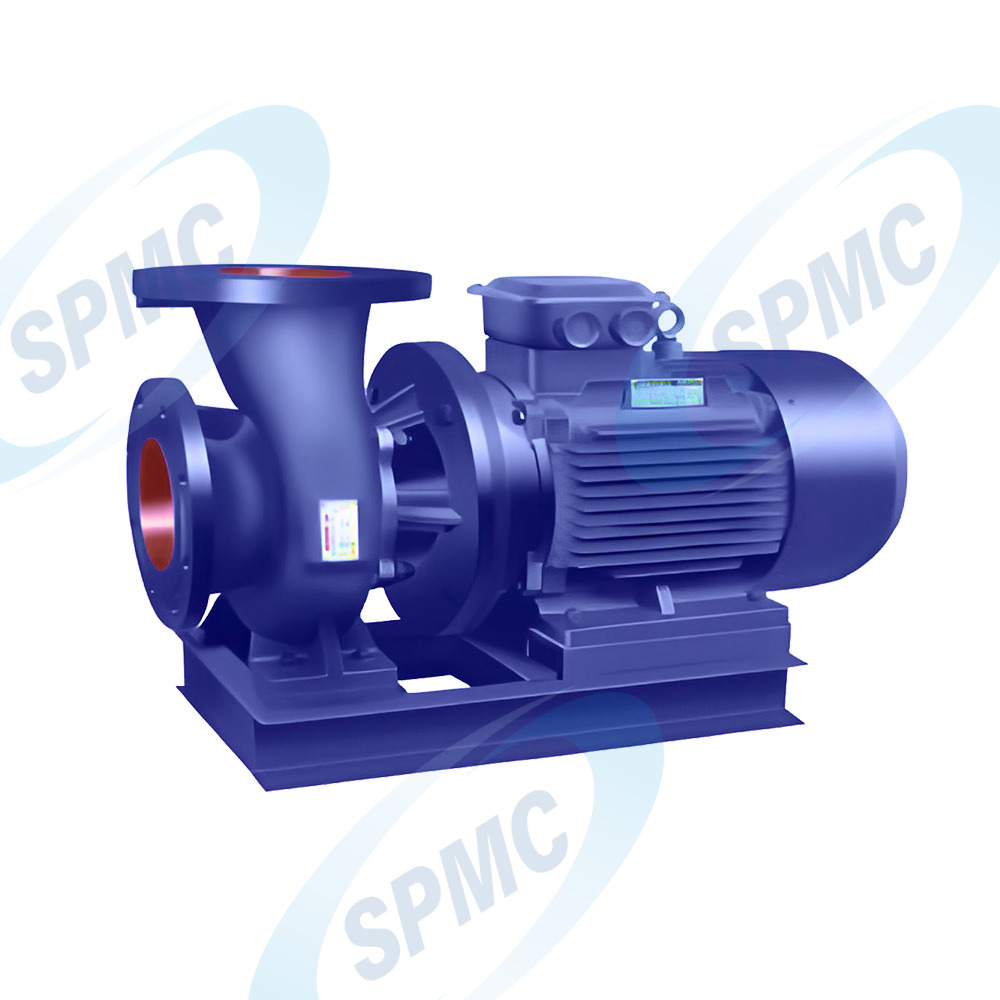
Internal parts dictate how your equipment performs under daily operational stress. We must look closely at the impellers first. You generally choose between closed, semi-open, and open designs. Closed impellers offer the absolute highest efficiency for clean fluids. Semi-open impellers handle slightly thicker liquids safely without clogging. Open impellers are absolutely mandatory for handling suspended solids and heavy abrasive slurries.
Next, you must consider the volute and outer casing carefully. The volute features a gradually expanding internal cross-section. This expanding area controls fluid velocity naturally. As the internal area increases, the fluid slows down proportionally. This deliberate slowing creates the final pressure needed for discharge into your piping.
Shafts and mechanical seals act as the primary failure points in any facility. You must balance seal types against strict plant leakage tolerances. You also need to account for fluid toxicity and strict environmental rules. A poorly chosen seal leads to dangerous leaks and premature bearing failure. Many engineers specify double mechanical seals when handling highly toxic chemicals.
You will see various structural configurations operating in modern industrial facilities. The standard horizontal centrifugal water pump remains highly popular globally. It offers excellent maintenance access for floor technicians. Crews can reach internal bearings without disconnecting the heavy main motor. This eases routine inspections significantly.
However, vertical inline designs save highly valuable facility floor space. Overhung designs also offer very compact footprints. They have a smaller physical presence but might complicate alignment slightly during installation. Facility layouts and existing piping designs often dictate which structural variation you choose ultimately.
Here is a quick reference chart for proper impeller selection:
Impeller Design | Optimal Fluid Type | Efficiency Level | Common Industrial Application |
|---|---|---|---|
Closed | Clean, clear liquids | Very High | Municipal water distribution systems |
Semi-Open | Light to medium debris | Moderate | Industrial process chemicals |
Open | Heavy slurries, raw solids | Lower | Wastewater treatment and mining |
Centrifugal mechanics possess very strict physical operational limits. They lose rapid efficiency when fluid viscosity rises too high. High shear stress occurs when fluids exceed certain centipoise (cP) thresholds. The spinning impeller struggles heavily to push thick, sticky fluids. This physical resistance results in massive electrical power consumption. It also drastically reduces the overall flow output delivered to the system.
The threat of cavitation remains a major reality for process engineers. You must clearly define the Net Positive Suction Head available (NPSHa). You then compare this figure directly against the NPSH required (NPSHr). If internal pressure drops below the liquid's specific vapor pressure, small bubbles form. These tiny vapor bubbles implode violently against the metal impeller. This violent physical action causes catastrophic impeller erosion over a short time.
Deadheading and water hammer pose severe systemic risks to your infrastructure. Operating a unit against closed discharge valves causes dangerous deadheading. The trapped fluid recirculates internally and overheats rapidly. This extreme heat leads to blown mechanical seals and warped metal shafts. Water hammer happens during abrupt, sudden flow changes in the system. The resulting kinetic shockwave routinely damages connected pipes, flanges, and valves.
Common Mistakes: Ignoring the NPSH safety margin is a frequent engineering error. Always ensure your NPSHa exceeds the NPSHr by at least three feet to prevent localized boiling.
Proper sizing ensures highly reliable daily operations in your plant. You must learn how to read the equipment performance curve accurately. Manufacturers provide these curves to illustrate operational capabilities. You cross-reference Total Dynamic Head (TDH) against the expected Flow Rate. Flow is usually measured in GPM or LPM. The intersection point on the graph shows the Best Efficiency Point (BEP).
Operating near the BEP minimizes internal vibration significantly. It also extends mechanical seal life and protects internal bearings. If you drift too far left or right on the curve, stress multiplies. System resistance also dictates your equipment selection heavily. You must precisely map the facility’s internal pipe friction. You also need to calculate vertical elevation changes and static head.
Energy consumption and scaling require careful, long-term technical evaluation.
Evaluate precise motor sizing to avoid wasted electrical power.
Consider adding variable frequency drives (VFDs) for flexible flow control.
Calculate long-term power usage to understand overall energy demands.
Monitor daily operational hours to schedule preventive maintenance accurately.
Avoid undersizing your main drive motor at all costs. An undersized motor will overheat during peak daily demand hours. Conversely, oversizing it wastes massive amounts of electricity daily.
Choosing the right manufacturing partner matters just as much as the hardware. You need strict engineering validation from any reputable centrifugal pump manufacturer. Buyers should always expect detailed, certified performance curves before issuing a purchase order. You should also request material test reports (MTRs) for critical wetted components. Vibration testing documentation must be provided prior to final equipment delivery.
Compliance and standards guarantee safety and long-term reliability. Ensure the manufacturer adheres strictly to industry-specific engineering frameworks. Look for API 610 compliance for volatile oil and gas applications. Check for ANSI B73.1 standards when handling aggressive chemical processing. ISO and strict hygienic standards apply directly to food, beverage, and pharmaceutical sectors.
Robust after-sales support defines long-term operational success. Evaluate the immediate availability of OEM replacement parts. You need localized maintenance support to minimize unexpected plant downtime. Clear, transparent warranty terms protect your initial capital investment against manufacturing defects.
Best Practices: Always request a certified performance test curve before finalizing your purchase order. Demand full material traceability for all highly stressed internal metal parts.
The fundamental working principle of centrifugal force is inherently simple. Yet, successful industrial application requires highly precise engineering alignment. Fluid dynamics must match your chosen mechanical hardware perfectly for safe operation. We strongly recommend readers audit their current system parameters today. Check your exact required flow rates and your total dynamic head pressure. Note any specific fluid properties like viscosity, temperature, and chemical makeup.
Gather these crucial details before you initiate vendor discussions. Take definitive action today to protect your facility. Encourage your technical buyers to request an application-specific curve analysis. Schedule a comprehensive site audit with a certified application engineer. Doing so ensures optimal specification and highly reliable daily operations for years to come.
A: Yes. Standard centrifugal pumps cannot evacuate air from the suction line independently. They rely entirely on flooded suction setups or specific self-priming configurations. If the inner casing is full of air, the spinning impeller cannot create the pressure differential needed to draw liquid. Always ensure the unit is fully primed with liquid before starting it.
A: Yes, but this requires specific internal mechanical configurations. You must use semi-open or fully open impeller designs. These open designs prevent rapid internal clogging. You also need hardened metallic materials to resist severe abrasion. Standard closed impellers will clog rapidly if exposed to heavy slurries or large solid debris.
A: Operating too far from the BEP causes severe mechanical stress. You will experience increased internal vibration and dangerously elevated bearing temperatures. This erratic operation heavily decreases your mechanical seal life. It also results in significantly higher energy expenditure, straining your electrical systems and reducing the equipment's overall functional lifespan.
A: A single-stage unit uses one impeller to generate discharge pressure. A multi-stage unit stacks multiple impellers on a single central shaft. As fluid passes from one impeller to the next, the discharge pressure multiplies steadily. It does this without proportionally increasing the flow rate, making it perfect for high-head applications.


